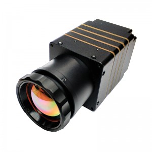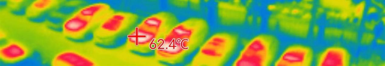
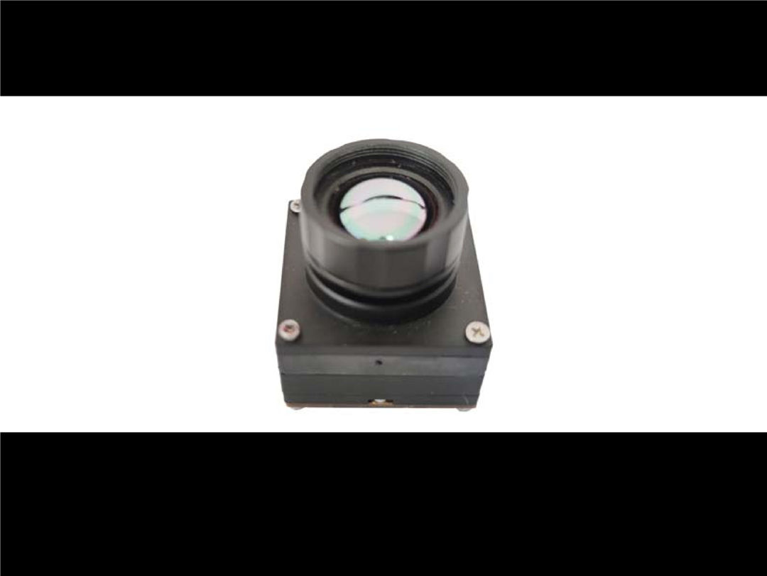
M384 infrared thermal imaging module
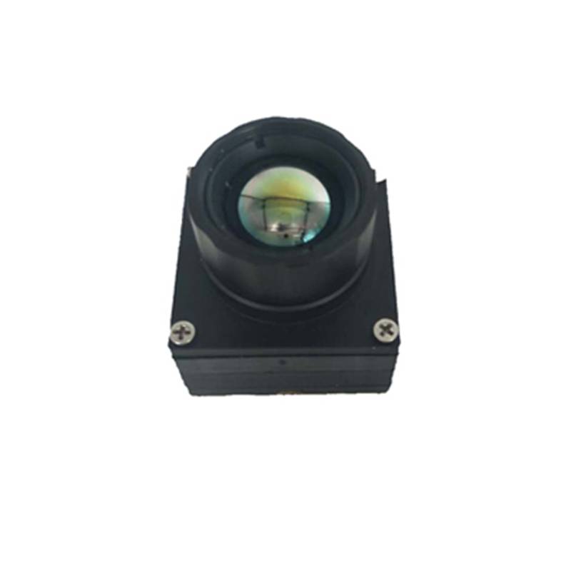
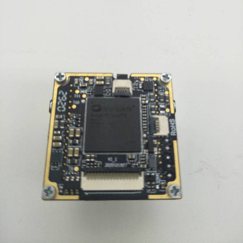
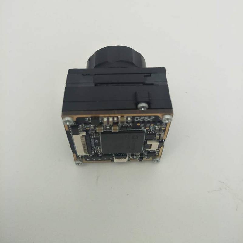
Thermal imaging module is based on ceramic packaging uncooled vanadium oxide infrared detector to develop a high performance infrared thermal imaging products, the products adopt parallel digital output interface, interface is rich, adaptive access a variety of intelligent processing platform, with high performance and low power consumption, small volume, easy to the characteristics of the development integration, can meet the application of various kinds of infrared measuring temperature of secondary development demand.
At present, the power industry is the most widely used industry of civil infrared thermal imaging equipment. As the most efficient and mature non-contact detection means, infrared thermal imager can greatly improve the progress of obtaining temperature or physical quantity, and further improve the operation reliability of power supply equipment. Infrared thermal imaging equipment plays a very important role in exploring the process of intelligence and super automation in the power industry.
Many inspection methods of surface defects of automobile parts are nondestructive testing method of coating chemicals. Therefore, the coated chemicals should be removed after inspection. Therefore, from the perspective of the improvement of the working environment and the health of the operators, it is required to use non-destructive testing methods without chemicals.
The following is a brief introduction of some chemical free nondestructive testing methods. These methods are to apply light, heat, ultrasonic, eddy current, current and other external excitation on the inspection object to change the temperature of the object, and use infrared thermal imager to carry out non-destructive inspection on the internal defects, cracks, internal peeling of the object, as well as welding, bonding, mosaic defects, density inhomogeneity and coating film thickness.
Infrared thermal imager nondestructive testing technology has the advantages of fast, non-destructive, non-contact, real-time, large area, remote detection and visualization. It is easy for practitioners to master the use method quickly. It has been widely used in mechanical manufacturing, metallurgy, aerospace, medical, petrochemical, electric power and other fields. With the development of computer technology, the intelligent monitoring and detection system of infrared thermal imager combined with computer has become a necessary conventional detection system in more and more fields.
Nondestructive testing is an applied technology subject based on modern science and technology. It is based on the premise of not destroying the physical characteristics and structure of the object to be tested. It uses physical methods to detect whether there are discontinuities (defects) in the interior or surface of the object, so as to judge whether the object to be tested is qualified, and then evaluate its practicability. At present, infrared thermal imager is based on non-contact, fast, and can measure the temperature of moving targets and micro targets. It can directly display the surface temperature field of objects with high temperature resolution (up to 0.01 ℃). It can use a variety of display methods, data storage and computer intelligent processing. It is mainly used in aerospace, metallurgy, machinery, petrochemical, machinery, architecture, natural forest protection and other fields Domain.
Product parameters
|
Type |
M384 |
|
Resolution |
384×288 |
|
Pixel space |
17μm |
|
|
93.0°×69.6°/4mm |
|
|
|
|
|
55.7°×41.6°/6.8mm |
|
FOV/Focal length |
|
|
|
28.4°x21.4°/13mm |
* Paralles interface in 25Hz output mode;
|
FPS |
25Hz | |
|
NETD |
≤60mK@f#1.0 | |
|
Working temperature |
-15℃~+60℃ | |
|
DC |
3.8V-5.5V DC | |
|
Power |
<300mW* | |
|
Weight |
<30g(13mm lens) |
|
|
Dimension(mm) |
26*26*26.4(13mm lens) |
|
|
Data interface |
parallel/USB | |
|
Control interface |
SPI/I2C/USB | |
|
Image intensification |
Multi-gear detail enhancement | |
|
Image calibration |
The shutter correction | |
|
Palette |
White glow/black hot/multiple pseudo-color plates |
|
|
Measuring range |
-20℃~+120℃(customized up to 550℃) |
|
|
Accuracy |
±3℃ or ±3% |
|
|
Temperature correction |
Manual /Automatic | |
|
Temperature statistics output |
Real-time parallel output | |
|
Temperature measurement statistics |
Support maximum /minimum statistics,temperature analysis |
|
user interface description
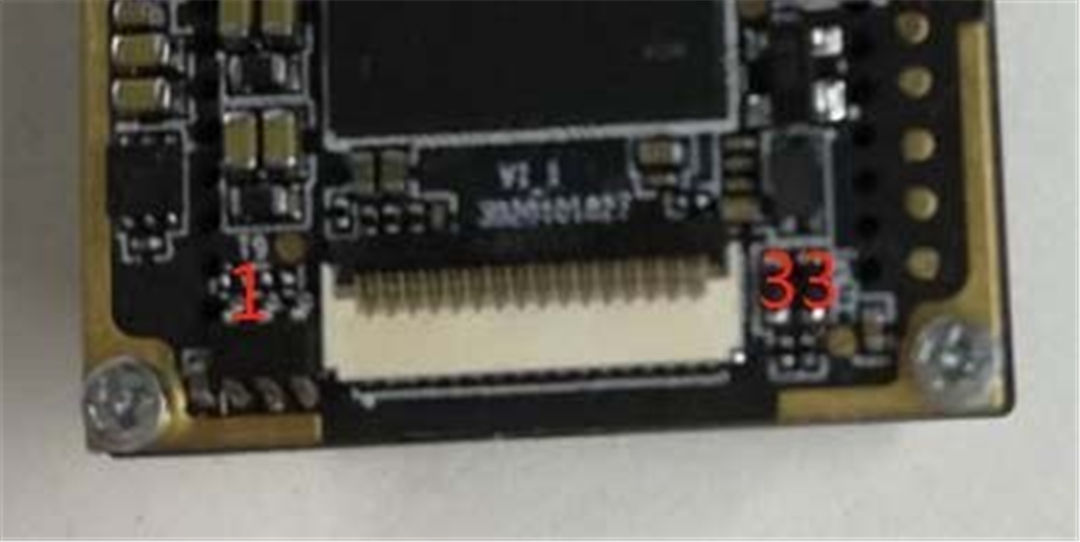
Figure1 user interface
The product adopts 0.3Pitch 33Pin FPC connector (X03A10H33G), and the input voltage is:3.8-5.5VDC, undervoltage protection is not supported.
Form 1 interface pin of thermal imager
| Pin number | name | type |
Voltage |
Specification | |
| 1,2 | VCC | Power | -- | Power supply | |
| 3,4,12 | GND | Power | -- | 地 | |
| 5 |
USB_DM |
I/O | -- |
USB 2.0 |
DM |
| 6 |
USB_DP |
I/O | -- | DP | |
| 7 |
USBEN* |
I | -- | USB enabled | |
| 8 |
SPI_SCK |
I |
Default:1.8V LVCMOS ; (if need 3.3V LVCOMS output, please contact us) |
SPI |
SCK |
| 9 |
SPI_SDO |
O | SDO | ||
| 10 |
SPI_SDI |
I | SDI | ||
| 11 |
SPI_SS |
I | SS | ||
| 13 |
DV_CLK |
O |
VIDEOl |
CLK | |
| 14 |
DV_VS |
O | VS | ||
| 15 |
DV_HS |
O | HS | ||
| 16 |
DV_D0 |
O | DATA0 | ||
| 17 |
DV_D1 |
O | DATA1 | ||
| 18 |
DV_D2 |
O | DATA2 | ||
| 19 |
DV_D3 |
O | DATA3 | ||
| 20 |
DV_D4 |
O | DATA4 | ||
| 21 |
DV_D5 |
O | DATA5 | ||
| 22 |
DV_D6 |
O | DATA6 | ||
| 23 |
DV_D7 |
O | DATA7 | ||
| 24 |
DV_D8 |
O |
DATA8 |
||
| 25 |
DV_D9 |
O |
DATA9 |
||
| 26 |
DV_D10 |
O |
DATA10 |
||
| 27 |
DV_D11 |
O |
DATA11 |
||
| 28 |
DV_D12 |
O |
DATA12 |
||
| 29 |
DV_D13 |
O |
DATA13 |
||
| 30 |
DV_D14 |
O |
DATA14 |
||
| 31 |
DV_D15 |
O |
DATA15 |
||
| 32 |
I2C_SCL |
I | SCL | ||
| 33 |
I2C_SDA |
I/O |
SDA |
||
communication adopts UVC communication protocol, image format is YUV422, if you need USB communication development kit, please contact us;
in PCB design, parallel digital video signal suggested 50 Ω impedance control.
Form 2 Electrical specification
Format VIN =4V, TA = 25°C
| Parameter | Identify |
Test condition |
MIN TYP MAX |
Unit |
| Input voltage range | VIN | -- |
3.8 4 5.5 |
V |
| Capacity | ILOAD | USBEN=GND |
75 300 |
mA |
| USBEN=HIGH |
110 340 |
mA | ||
|
USB enabled control |
USBEN-LOW | -- |
0.4 |
V |
| USBEN- HIGN | -- |
1.4 5.5V |
V |
Form 3 Absolute Maximum rating
| Parameter | Range |
| VIN to GND | -0.3V to +6V |
| DP,DM to GND | -0.3V to +6V |
| USBEN to GND | -0.3V to 10V |
| SPI to GND | -0.3V to +3.3V |
| VIDEO to GND | -0.3V to +3.3V |
| I2C to GND | -0.3V to +3.3V |
|
Storage temperature |
−55°C to +120°C |
| Operating temperature | −40°C to +85°C |
Note: Ranges listed that meet or exceed absolute maximum ratings may cause permanent damage to the product.This is just a stress rating;Don't mean that the functional operation of the Product under these or any other conditions is higher than those described in the operations section of this specification. Prolonged operations that exceed maximum working conditions may affect the reliability of the product.
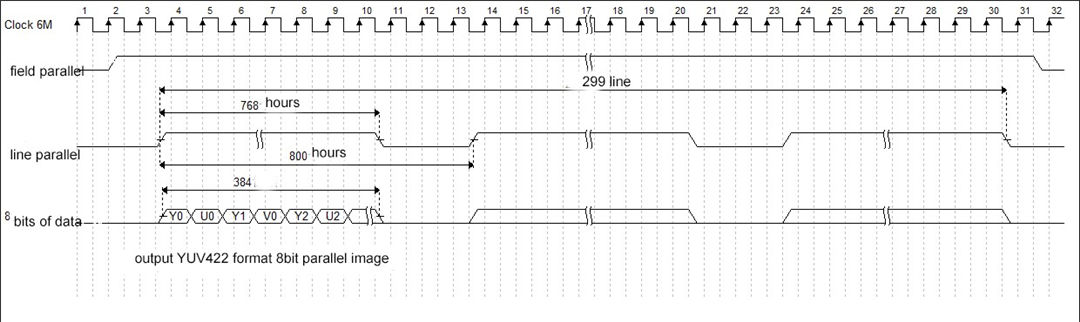
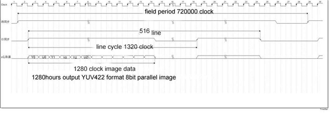
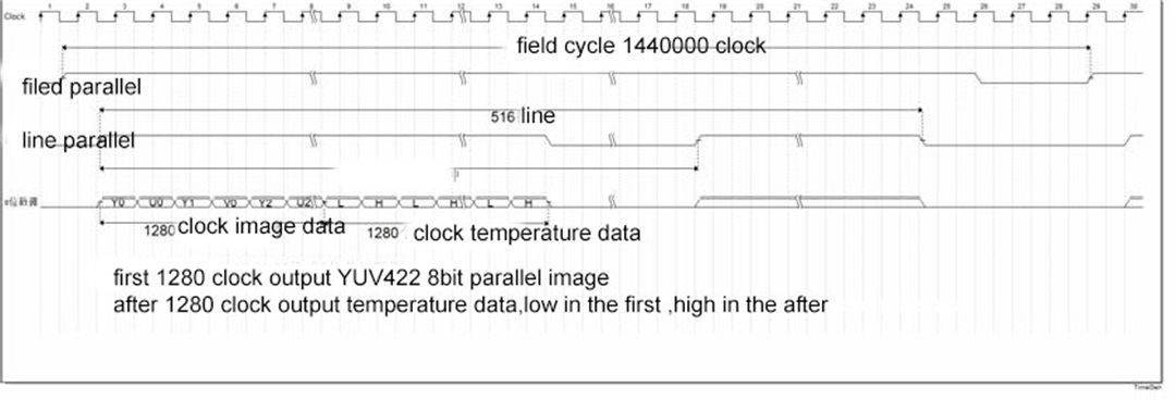
Digital interface output sequence diagram(T5)
Figure: 8bit Parallel image
M384
M640
M384
M640
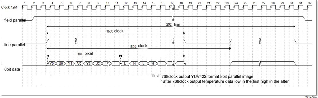
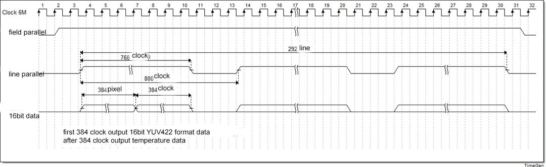
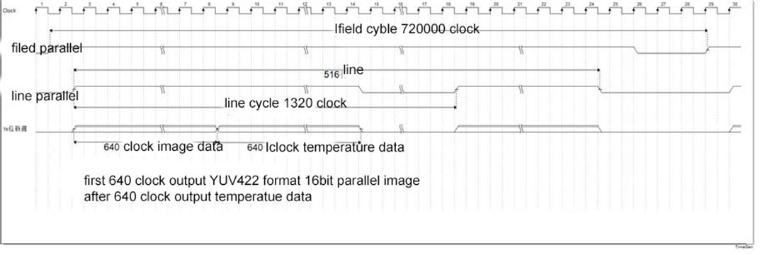
Figure: 16bit Parallel image and temperature data
M384
M640
Attention
(1) It is recommended to use Clock rising edge sampling for data;
(2) Field synchronization and line synchronization are both highly effective;
(3) The image data format is YUV422, the data low bit is Y, and the high bit is U/V;
(4) The temperature data unit is (Kelvin (K) *10), and the actual temperature is read value /10-273.15 (℃).
Caution
To protect you and others from injury or to protect your device from damage, please read all of the following information before using your device.
1. Do not look directly at the high-intensity radiation sources such as the sun for the movement components;
2. Do not touch or use other objects to collide with the detector window;
3. Do not touch the equipment and cables with wet hands;
4. Do not bend or damage the connecting cables;
5. Do not scrub your equipment with diluents;
6. Do not unplug or plug other cables without disconnecting the power supply;
7. Do not connect the attached cable incorrectly to avoid damaging the equipment;
8. Please pay attention to prevent static electricity;
9. Please do not disassemble the equipment. If there is any fault, please contact our company for professional maintenance.
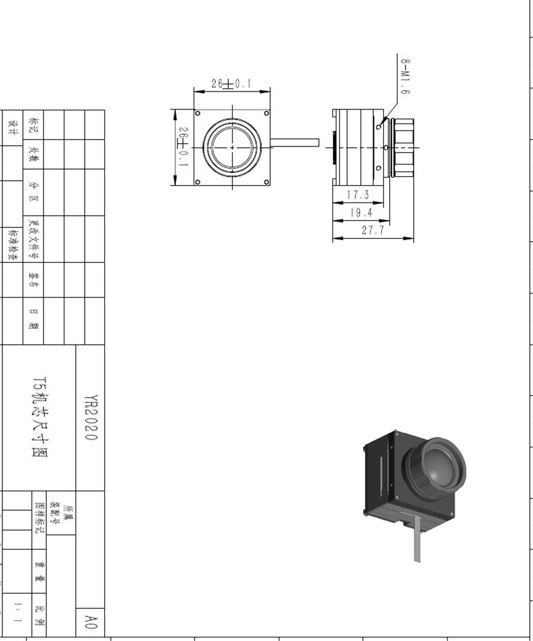
picture view
Mechnical interface dimension drawing