Thermal Design And Management
Overheating (temperature rise) has always been the enemy of stable and reliable product operation. When thermal management R&D personnel do product demonstration and design, they need to take care of the needs of different market entities and achieve the best balance between performance indicators and comprehensive costs.
Because electronic components are basically affected by the temperature parameter, such as the thermal noise of the resistor, the decrease of the PN junction voltage of the transistor under the influence of temperature rise, and the inconsistent capacitance value of the capacitor at high and low temperatures.
With the flexible use of thermal imaging cameras, R&D personnel can greatly improve the work efficiency of all aspects of heat dissipation design.
Thermal management
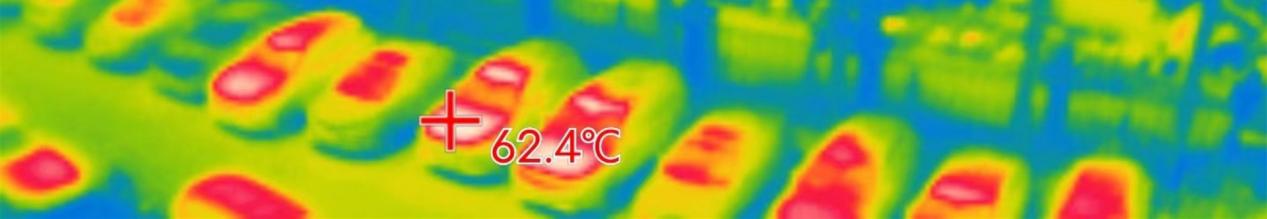
1. Quickly evaluate the heat load
Thermal imaging camera can visually image the temperature distribution of the product, helping R&D personnel to accurately evaluate the thermal distribution, locate the area with excessive heat load, and make the subsequent heat dissipation design more targeted.
As shown in the figure below, the redder means the higher the temperature.。
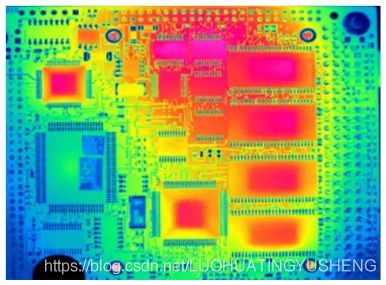
▲PCB board
2. Evaluation and verification of heat dissipation scheme
There will be a variety of heat dissipation schemes in the design stage. The thermal imaging camera can help R&D personnel quickly and intuitively evaluate different heat dissipation schemes and determine the technical route.
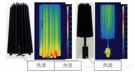
For example, placing a discrete heat source on a large metal radiator will generate a large thermal gradient because the heat is slowly conducted through the aluminum to the fins (fins).
The R&D personnel plan to implant heat pipes in the radiator to reduce the thickness of the radiator plate and the area of the radiator, reduce the dependence on forced convection so as to reduce noise, and ensure the long-term stable operation of the product. The thermal imaging camera can be very helpful to engineers evaluate the effectiveness of the program
The picture above explains:
► Heat source power 150W;
►Left picture: traditional aluminum heat sink, length 30.5cm, base thickness 1.5cm, weight 4.4kg, it can be found that the heat is diffused gradually with the heat source as the center;
►Right picture: The heat sink after 5 heat pipes is implanted, the length is 25.4cm, the base thickness is 0.7cm, and the weight is 2.9kg.
Compared with the traditional heat sink, the material is reduced by 34%. It can be found that the heat pipe can take away the heat isothermally and the radiator temperature The distribution is uniform, and it is found that only 3 heat pipes are required for heat conduction, which may further reduce the cost.
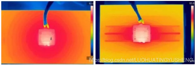
Further, R&D personnel need to design the layout and contact of the heat source and heat pipe radiator. With the help of infrared thermal imaging cameras, R&D personnel found that the heat source and radiator can use heat pipes to realize the isolation and transmission of heat, which makes the design of the product more flexible.
The picture above explains:
► Heat source power 30W;
►Left picture: The heat source is in direct contact with the traditional heat sink, and the temperature of the heat sink presents an obvious thermal gradient distribution;
►Right picture: The heat source isolates the heat to the heat sink through the heat pipe. It can be found that the heat pipe transfers heat isothermally, and the temperature of the heat sink is evenly distributed; the temperature at the far end of the heat sink is 0.5°C higher than the near end, because the heat sink heats the surrounding air The air rises and gathers and heats the far end of the radiator;
► R&D personnel can further optimize the design of the number, size, location, and distribution of heat pipes.
Post time: Dec-29-2021